|
APPLICATION:
The Test Terminal Block connected with Ammeters, KWH meters,
Maximum Demand Indicators, Trivector Meters etc. enables site
testing to be made without disconnecting the existing wiring
leading to the consumers or to the meters. Any connection
like insertion of current or voltage coils of testing instruments
or shorting of the CT secondary winding can be easily and
quickly made. The Test Terminal Blocks are therefore principally
intended for use in connection with stationary high voltage
measuring unit. With slight modifications they can also be
used for testing relays and other testing equipment.
DESCRIPTION:
For each current circuits there are three terminal inserts
each with entry at the top and back of the Block for back
connected Test Terminal Blocks(suitable for mounting on the
front of the panel and connections from back and test connections
from side outside the panel) and entry from the top and bottom(generally
suitable for surface mounting inside the panel). A link bar,
insulated from the terminal insert, is provided along the
axis of the block, across each set of three inserts by means
of three cheese headed screws in the A lin bar for screw type
Test Terminal Blocks and two hooks shorting / linking the
three current terminals in case of link type Blocks. The terminal
inserts can be connected or disconnected as may be necesary
for testing. It is therefore possible to connect current coil
of testing instruments in series with the meter without removing
the connection wires. Thus operating to testing condition
can be achieved without interrupting the current and voltage
circuits.
The Voltage terminals are so designed that incoming and outgoing
leads can be connected or disconnected by means of a movable
link. Large entries are provided in the bakelite case so that
two or more wires can be connected if so required. The links
are connected to the terminals by means of a screw.
When several meters are tested, their current coils should
be connected in series. If meters are to be tested individually,
separate Test Terminal Blocks are required for each meter.
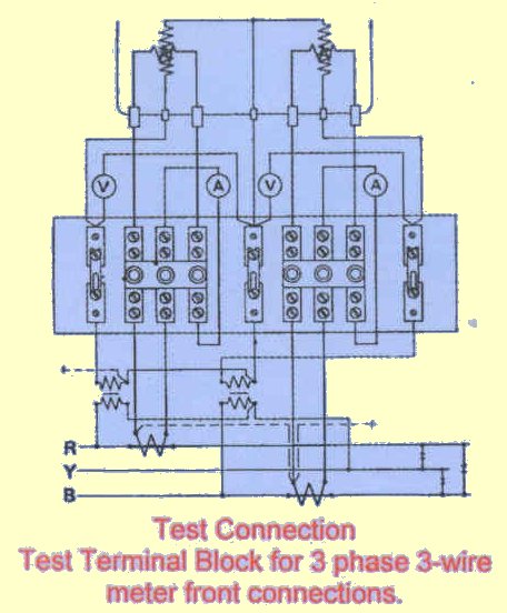
Operating and Test Connections are pasted in the cover of
each of the Blocks. They are also shown along side for one
of the types, for illustration.
TYPES:
Test Terminal Blocks are available in 3 phase,
3 wire or 3 phase 4 wire front or back connected up to 50
Amps. Both link and screw type arrangements for CT shorting
are manufactured by us. Test Terminal Blocks are provided
with covers made of phenolic moulding powder for safety.
TECHNICAL DATA:
| Maximum rated current |
50A |
| Maximum rated voltage |
660V |
| Diameters of entries |
5.5 mm |
TYPES AND CODE NO.:
| Test Terminal Block L3 phase 3 wire L for
front connection screw type |
DAV 3.1 |
| Test Terminal Block L3 phase 3 wire L for
front connection link type |
DAV 3.2 |
| Test Terminal Block L3 phase
3 wire L for back connection screw type |
DAV 3.3 |
| Test Terminal Block L3 phase 3 wire L for
back connection link type |
DAV 3.4 |
| Test Terminal Block L3 phase 4 wire L for
front connection screw type |
DAV 4.1 |
| Test Terminal Block L3 phase 4 wire L for
front connection link type |
DAV 4.2 |
| Test Terminal Block L3 phase
4 wire L for back connection screw type |
DAV 4.3 |
| Test Terminal Block L3 phase 4 wire L for
back connection link type |
DAV 4.3 |
|